АвтоАвтоматизацияАрхитектураАстрономияАудитБиологияБухгалтерияВоенное делоГенетикаГеографияГеологияГосударствоДомДругоеЖурналистика и СМИИзобретательствоИностранные языкиИнформатикаИскусствоИсторияКомпьютерыКулинарияКультураЛексикологияЛитератураЛогикаМаркетингМатематикаМашиностроениеМедицинаМенеджментМеталлы и СваркаМеханикаМузыкаНаселениеОбразованиеОхрана безопасности жизниОхрана ТрудаПедагогикаПолитикаПравоПриборостроениеПрограммированиеПроизводствоПромышленностьПсихологияРадиоРегилияСвязьСоциологияСпортСтандартизацияСтроительствоТехнологииТорговляТуризмФизикаФизиологияФилософияФинансыХимияХозяйствоЦеннообразованиеЧерчениеЭкологияЭконометрикаЭкономикаЭлектроникаЮриспунденкция
Research of microstructures in polarizing light
System from a polarizer and the analyzer - a basis of the devices used for researches in polarized light. The polarizer and the analyzer are located along a direction of light beams between which the investigated object is located. The analyzer is arranged similarly to a polarizer, but adapted for rotation around of a longitudinal axis of system. If planes of polarizer П and planes of analyzer A coincide, light completely passes through the analyzer and forms on screen Э a light spot (fig. 5, and; polarizer П and the analyzer A - polarizing thin layer, a plane of fluctuations, which are designated by arrows). At turn of the analyzer brightness of a spot on the screen decreases.
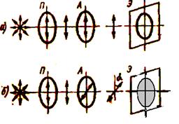
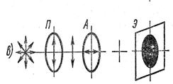
Fig. 5.
Decrease of intensity I of light which has been last through the analyzer) occurs on a parity  ,
,  , intensity of light which has been last through a polarizer and the analyzer accordingly, α - a corner of turn of a plane of analyzer (fig. 5,). At mutually perpendicular arrangement of planes of a polarizer and the analyzer light is completely extinguished (fig. 5,) by the analyzer. Thus, for one full turn (on 360) the analyzer the screen two times is completely shined also two times is completely blacked out. Polarized light is applied at research of anisotropic elements of different structures, in particular fabrics of an organism. In many cases thus probably to establish arrangement and a structure of elements of structure which are not visible at supervision in a microscope in natural light.
Optical anisotropy is observed, for example, at muscular, connecting (collagenic) nervous fibres. Therefore the name of skeletal muscles - cross-striated - is connected by that by consideration in a microscope in natural light the fibre looks as alter nating more dark and more light sites. Research of a muscular fibre in polarized light finds out, that more dark sites are anisotropic whereas more light - isotropic, as is the reason of their distinction in natural light.
Collagenic tissues are anisotropic, their optical axis is located along an axis of a fibre. Micellas in a soft environment of neurofibril are also anisotropic, but their opticalaxes are located in radial directions. The polarizing microscope is applied to histologic research of these structures. It is a biological microscope, with two Nicol prisms one is located in front of the condenser and serves as a polarizer, the second - between an objective and ocular - serves as a analyzer. A subject little table rotate around of a longitudinal axis of a microscope on 3600. If in the polarizing microscope, established on full blackout of a field of vision, to place a preparation with isotropic structure, the field of vision remains dark. In case of when between a polarizer and the analyzer the preparation with anisotropic structures is placed, light which has been last a polarizer, in them will refract again doubly. In this connection it is not extinguished completely by the analyzer and corresponding structures will be light on the general dark background of a field of vision. As an example on fig. 6 the microphoto of a thin cut of the bone, received by means of a polarizing microscope is shown. On a cut collagenic fibres which are visible only lay in a plane of a cut. The fibres located perpendicularly of a plane of a cut, through which light passes along an optical axis, remain invisible.
Поиск по сайту: