АвтоАвтоматизацияАрхитектураАстрономияАудитБиологияБухгалтерияВоенное делоГенетикаГеографияГеологияГосударствоДомДругоеЖурналистика и СМИИзобретательствоИностранные языкиИнформатикаИскусствоИсторияКомпьютерыКулинарияКультураЛексикологияЛитератураЛогикаМаркетингМатематикаМашиностроениеМедицинаМенеджментМеталлы и СваркаМеханикаМузыкаНаселениеОбразованиеОхрана безопасности жизниОхрана ТрудаПедагогикаПолитикаПравоПриборостроениеПрограммированиеПроизводствоПромышленностьПсихологияРадиоРегилияСвязьСоциологияСпортСтандартизацияСтроительствоТехнологииТорговляТуризмФизикаФизиологияФилософияФинансыХимияХозяйствоЦеннообразованиеЧерчениеЭкологияЭконометрикаЭкономикаЭлектроникаЮриспунденкция
Lesson 13
|
Читайте также: |
Measuring generators. Basic parameters of measuring generators. Generalized block diagram of the measuring generators. Generators of harmonic (sinusoidal) signals. LFO. High-frequency generator. Pulse generators. Generators of random signals.
In electricity generation, a generator is a device that converts mechanical energy to electrical energy for use in an external circuit. The source of mechanical energy may vary widely from a hand crank to an internal combustion engine. Generators provide nearly all of the power for electric power grids.
The reverse conversion of electrical energy into mechanical energy is done by an electric motor, and motors and generators have many similarities. Many motors can be mechanically driven to generate electricity and frequently make acceptable generators.
Electromagnetic generators fall into one of two broad categories, dynamos and alternators.
· Dynamos generate direct current, usually with voltage and/or current fluctuations, usually through the use of a commutator
· Alternators generate alternating current, which may be rectified by another (external or directly incorporated) system.
Mechanical:
· Rotor: The rotating part of an electrical machine
· Stator: The stationary part of an electrical machine
Electrical:
· Armature: The power-producing component of an electrical machine. In a generator, alternator, or dynamo the armature windings generate the electric current. The armature can be on either the rotor or the stator.
· Field: The magnetic field component of an electrical machine. The magnetic field of the dynamo or alternator can be provided by either electromagnets or permanent magnets mounted on either the rotor or the stator.
· The operating principle of electromagnetic generators was discovered in the years of 1831–1832 by Michael Faraday. The principle, later called Faraday's law, is that an electromotive force is generated in an electrical conductor which encircles a varying magnetic flux.
· He also built the first electromagnetic generator, called the Faraday disk, a type of homopolar generator, using a copper disc rotating between the poles of a horseshoe magnet. It produced a small DC voltage.
· This design was inefficient, due to self-cancelling counterflows of current in regions that were not under the influence of the magnetic field. While current was induced directly underneath the magnet, the current would circulate backwards in regions that were outside the influence of the magnetic field. This counterflow limited the power output to the pickup wires, and induced waste heating of the copper disc. Later homopolar generators would solve this problem by using an array of magnets arranged around the disc perimeter to maintain a steady field effect in one current-flow direction.
· Another disadvantage was that the output voltage was very low, due to the single current path through the magnetic flux. Experimenters found that using multiple turns of wire in a coil could produce higher, more useful voltages. Since the output voltage is proportional to the number of turns, generators could be easily designed to produce any desired voltage by varying the number of turns. Wire windings became a basic feature of all subsequent generator designs.
· Independently of Faraday, the Hungarian Anyos Jedlik started experimenting in 1827 with the electromagnetic rotating devices which he called electromagnetic self-rotors. In the prototype of the single-pole electric starter (finished between 1852 and 1854) both the stationary and the revolving parts were electromagnetic. He also may have formulated the concept of the dynamo in 1861 (before Siemens andWheatstone) but didn't patent it as he thought he wasn't the first to realize this.[1]
Direct current generators[edit]
Main article: Dynamo
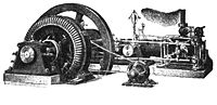
This large belt-driven high-current dynamoproduced 310 amperes at 7 volts. Dynamos are no longer used due to the size and complexity of thecommutator needed for high power applications.
The dynamo was the first electrical generator capable of delivering power for industry. The dynamo uses electromagnetic induction to convert mechanical rotation into direct current through the use of a commutator. An early dynamo was built byHippolyte Pixii in 1832.
The modern dynamo, fit for use in industrial applications, was invented independently by Sir Charles Wheatstone, Werner von Siemens and Samuel Alfred Varley. Varley took out a patent on 24 December 1866, while Siemens and Wheatstone both announced their discoveries on 17 January 1867, the latter delivering a paper on his discovery to the Royal Society.
The "dynamo-electric machine" employed self-powering electromagnetic field coils rather than permanent magnets to create the stator field.[2] Wheatstone's design was similar to Siemens', with the difference that in the Siemens design the stator electromagnets were in series with the rotor, but in Wheatstone's design they were in parallel.[3] The use of electromagnets rather than permanent magnets greatly increased the power output of a dynamo and enabled high power generation for the first time. This invention led directly to the first major industrial uses of electricity. For example, in the 1870s Siemens used electromagnetic dynamos to power electric arc furnaces for the production of metals and other materials.
The dynamo machine that was developed consisted of a stationary structure, which provides the magnetic field, and a set of rotating windings which turn within that field. On larger machines the constant magnetic field is provided by one or more electromagnets, which are usually called field coils.
Large power generation dynamos are now rarely seen due to the now nearly universal use of alternating current for power distribution. Before the adoption of AC, very large direct-current dynamos were the only means of power generation and distribution. AC has come to dominate due to the ability of AC to be easily transformed to and from very high voltages to permit low losses over large distances.
Alternating current generators[edit]
Main article: Alternator
Ferranti alternating current generator, c. 1900.
Through a series of discoveries, the dynamo was succeeded by many later inventions, especially the AC alternator, which was capable of generating alternating current.
Alternating current generating systems were known in simple forms from Michael Faraday's original discovery of the magnetic induction of electric current. Faraday himself built an early alternator. His machine was a "rotating rectangle", whose operation was heteropolar - each active conductor passed successively through regions where the magnetic field was in opposite directions.[4]
Large two-phase alternating current generators were built by a British electrician, J.E.H. Gordon, in 1882. The first public demonstration of an "alternator system" was given by William Stanley, Jr., an employee of Westinghouse Electric in 1886.[5]
Sebastian Ziani de Ferranti established Ferranti, Thompson and Ince in 1882, to market his Ferranti-Thompson Alternator, invented with the help of renowned physicist Lord Kelvin.[6] His early alternators produced frequencies between 100 and 300 Hz. Ferranti went on to design the Deptford Power Station for the London Electric Supply Corporation in 1887 using an alternating current system. On its completion in 1891, it was the first truly modern power station, supplying high-voltage AC power that was then "stepped down" for consumer use on each street. This basic system remains in use today around the world.
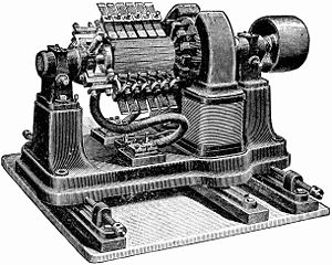
A small early 1900s 75 kVAdirect-driven power station AC alternator, with a separate belt-driven exciter generator.
In 1891, Nikola Tesla patented a practical "high-frequency" alternator (which operated around 15 kHz).[7] After 1891, polyphase alternators were introduced to supply currents of multiple differing phases.[8] Later alternators were designed for varying alternating-current frequencies between sixteen and about one hundred hertz, for use with arc lighting, incandescent lighting and electric motors.[9]
Self-excitation[edit]
Main article: Excitation (magnetic)
As the requirements for larger scale power generation increased, a new limitation rose: the magnetic fields available from permanent magnets. Diverting a small amount of the power generated by the generator to an electromagnetic field coil allowed the generator to produce substantially more power. This concept was dubbed self-excitation.
The field coils are connected in series or parallel with the armature winding. When the generator first starts to turn, the small amount of remanent magnetism present in the iron core provides a magnetic field to get it started, generating a small current in the armature. This flows through the field coils, creating a larger magnetic field which generates a larger armature current. This "bootstrap" process continues until the magnetic field in the core levels off due to saturation and the generator reaches a steady state power output.
Very large power station generators often utilize a separate smaller generator to excite the field coils of the larger. In the event of a severe widespread power outage whereislanding of power stations has occurred, the stations may need to perform a black start to excite the fields of their largest generators, in order to restore customer power service.
Specialized types of generator[edit]
Direct current[edit]
Homopolar generator[edit]
Main article: Homopolar generator
A homopolar generator is a DC electrical generator comprising an electrically conductive disc or cylinder rotating in a plane perpendicular to a uniform static magnetic field. A potential difference is created between the center of the disc and the rim (or ends of the cylinder), the electrical polarity depending on the direction of rotation and the orientation of the field.
It is also known as a unipolar generator, acyclic generator, disk dynamo, or Faraday disc. The voltage is typically low, on the order of a few volts in the case of small demonstration models, but large research generators can produce hundreds of volts, and some systems have multiple generators in series to produce an even larger voltage.[11]They are unusual in that they can produce tremendous electric current, some more than a million amperes, because the homopolar generator can be made to have very low internal resistance.
MHD generator[edit]
Main article: MHD generator
A magnetohydrodynamic generator directly extracts electric power from moving hot gases through a magnetic field, without the use of rotating electromagnetic machinery. MHD generators were originally developed because the output of a plasma MHD generator is a flame, well able to heat the boilers of a steam power plant. The first practical design was the AVCO Mk. 25, developed in 1965. The U.S. government funded substantial development, culminating in a 25 MW demonstration plant in 1987. In the Soviet Union from 1972 until the late 1980s, the MHD plant U 25 was in regular commercial operation on the Moscow power system with a rating of 25 MW, the largest MHD plant rating in the world at that time.[12] MHD generators operated as a topping cycle are currently (2007) less efficient than combined cycle gas turbines.
Alternating current[edit]
Induction generator[edit]
Main article: induction generator
Some AC motors may be used as generators, turning mechanical energy into electrical current. Induction generators operate by mechanically turning their rotor faster than the synchronous speed, giving negative slip. A regular AC asynchronous motor usually can be used as a generator, without any internal modifications. Induction generators are useful in applications such as minihydro power plants, wind turbines, or in reducing high-pressure gas streams to lower pressure, because they can recover energy with relatively simple controls.
To operate an induction generator must be excited with a leading voltage; this is usually done by connection to an electrical grid, or sometimes they are self-excited by using phase correcting capacitors.
Linear electric generator[edit]
Main article: Linear alternator
In the simplest form of linear electric generator, a sliding magnet moves back and forth through a solenoid - a spool of copper wire. An alternating current is induced in the loops of wire by Faraday's law of induction each time the magnet slides through. This type of generator is used in the Faraday flashlight. Larger linear electricity generators are used in wave power schemes.
Variable speed constant frequency generators[edit]
Many renewable energy efforts attempt to harvest natural sources of mechanical energy (wind, tides, etc) to produce electricity. Because these sources fluctuate in power applied, standard generators using permanent magnets and fixed windings would deliver unregulated voltage and frequency. The overhead of regulation (whether before the generator via gear reduction or after generation by electrical means) is high in proportion to the naturally-derived energy available.
New generator designs such as the asynchronous or induction singly fed generator, the doubly fed generator, or the brushless wound-rotor doubly fed generator are seeing success in variable speed constant frequency applications, such as wind turbines or other renewable energy technologies. These systems thus offer cost, reliability and efficiency benefits in certain use cases.
Схема замещения [ править ]

Схема замещения генератора и нагрузки.
G = генератор
V G = генератор напряжение холостого хода
R G = генератор внутреннее сопротивление
V L = напряжение генератора под нагрузкой
R L = сопротивление нагрузки
Эквивалентная схема генератора и нагрузки показана на рисунке справа. Генератор представлена в абстрактной генератора, состоящей из идеального источника напряжения и внутреннего сопротивления. Генератора  и
и  параметры могут быть определены путем измерения сопротивление обмотки (с поправкой на рабочей температуре), и измерения холостого хода и загружаются напряжения для заданного тока нагрузки.
Это простейшая модель генератора, дополнительные элементы, возможно, потребуется добавить для точного представления. В частности, индуктивность может быть добавлен, чтобы обеспечить обмоток конструкции станка, потока магнитного утечки, [ 16 ], но полный представление может стать гораздо сложнее, чем это. [ 17 ]
Поиск по сайту: