АвтоАвтоматизацияАрхитектураАстрономияАудитБиологияБухгалтерияВоенное делоГенетикаГеографияГеологияГосударствоДомДругоеЖурналистика и СМИИзобретательствоИностранные языкиИнформатикаИскусствоИсторияКомпьютерыКулинарияКультураЛексикологияЛитератураЛогикаМаркетингМатематикаМашиностроениеМедицинаМенеджментМеталлы и СваркаМеханикаМузыкаНаселениеОбразованиеОхрана безопасности жизниОхрана ТрудаПедагогикаПолитикаПравоПриборостроениеПрограммированиеПроизводствоПромышленностьПсихологияРадиоРегилияСвязьСоциологияСпортСтандартизацияСтроительствоТехнологииТорговляТуризмФизикаФизиологияФилософияФинансыХимияХозяйствоЦеннообразованиеЧерчениеЭкологияЭконометрикаЭкономикаЭлектроникаЮриспунденкция
Power and energy measurement in DC and AC. Measurement of the total, active, reactive power and power factor
If a product uses power, then power consumption and power quality measurements must be made as part of product design and test. These measurements are essential to optimize product design, comply with standards and provide nameplate information to customers.
This lesson will discuss best practices for making these measurements, starting with power measurement basics and proceeding to the types of instruments and associated components typically used to make measurements. The lesson will conclude with real-world examples, which apply the information imparted earlier in the article to solve practical measurement problems. Although most of us have been exposed to basic power measurement equations, a primer is helpful to summarize this information and to show how it applies to product design and test.
Power Measurement Basics
DC power measurement is relatively simple as the equation is simply watts = volts x amps. For AC power measurement, the power factor (PF) introduces complexity as watts = volts x amps x PF. This measurement of AC power is referred to as active power, true power or real power. In AC systems, multiplying volts x amps = volt-amps, also called apparent power.
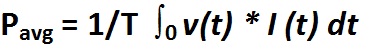
Power consumption is measured by calculating it over time, using at least one complete cycle. Using digitizing techniques, the instantaneous voltage is multiplied by the instantaneous current then accumulated and integrated over a specific time period to provide a measurement. This method provides a true power measurement and true RMS measurements for any waveform, sine or distorted, including harmonic content up to the bandwidth of the instrument.
Single-Phase and three-Phase Power Measurement
The Blondel Transformation states that total power is measured with one less wattmeter than the number of wires in the system. So, a single-phase, two-wire system will require one wattmeter, a single-phase, three-wire system will require two wattmeters (Figure 1), a three-phase, three-wire system will require two wattmeters, and a three-phase, four-wire system will require three watt meters.
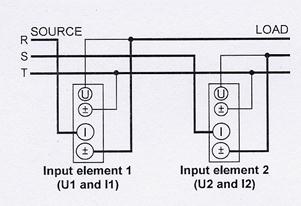

Figure 1. The two-wattmeter method can measure power through direct connections to a 3P3W system. Pt = P1 + P2
In this context, a wattmeter is a device that measures power using one current and one voltage input. Many Power Analyzers and DSOs have multiple current/voltage input pairs capable of measuring watts, in effect acting as multiple wattmeters within a single instrument. Thus, it’s possible to measure three-phase 4-wire power with one correctly specified Power Analyzer.
With a single-phase, two-wire system (Figure 2), the voltage and current detected by the wattmeter are equal to the total power dissipated by the load. The voltage is measured between the two wires, and the current is measured in the wire supplying power to the load, often called the hot wire. Voltage can typically be measured directly by a Power Analyzer up to 1000 V RMS. Higher voltages will require the use of a VT (Voltage Transformer) on an AC system to step down the voltage to a level that can be measured by the instrument. Currents can typically be measured directly by a Power Analyzer up to 50 A, depending on the instrument. Higher currents will require the use of a CT (Current Transformer) on an AC system. There are different types of CT’s. Some are placed directly in-line. Others have a window which the current-carrying cable passes through. The third kind is a clamp-on type. For DC currents, a shunt is typically used. The shunt is placed in line and a low level millivolt signal is measured by the instrument.
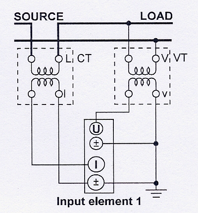
Figure 2. A Single phase, two-wire system uses a current transformer and voltage transformer.
With a single-phase, three-wire system (Figure 3), the total power is the algebraic sum of the two wattmeter readings. Each wattmeter is connected from one of the hot wires to the neutral, and current is measured in each hot wire. Total Power is calculated as Pt = P1 + P2.
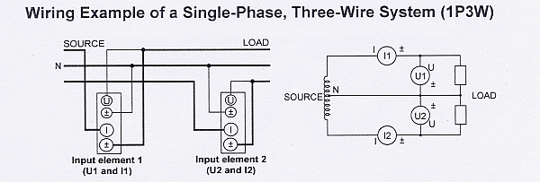
Figure 3. Two wattmeters connect to a single-phase, three-wire system (1P3W).
With a three-phase, four-wire system (Figure 4), the three wattmeters each measure voltage from a hot wire to the neutral, and each wattmeter measures current in one of three hot wires. The total power for the three phases is the algebraic sum of the three wattmeter measurements, as each meter is in essence measuring a single phase of the three-phase system. Pt = P1 + P2 + P3
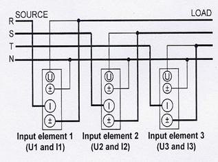
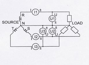
Figure 4. This three-phase, four-wire system uses three wattmeters.
With a three-phase 3-wire system (Figure 5), the two wattmeters measure phase current in any two of three wires. Each wattmeter measures a line-to-line voltage between two of the three power supply lines. In this configuration, the total power, watts, is accurately measured by the algebraic sum of the two wattmeter values. Pt = P1 + P2. This holds true if the system is balanced or unbalanced.
Power Factor Measurement
Power factor must often be measured, and this value should be kept as close as possible to unity (1.0)
In an electric power system, a load with a low power factor draws more current than a load with a high power factor for the same amount of useful power transferred. The higher currents increase the energy lost in the distribution system and require larger wires and other equipment. Because of the costs of larger equipment and wasted energy, electrical utilities will usually charge a higher cost to industrial or commercial customers exhibiting a low power factor. If power-consuming devices have good power factors, then the entire power system will as well, and vice versa. When power factors drop, power-factor-correction devices must often be used, at considerable expense. These devices are typically capacitors because the bulk of most power-consumption loads are inductive.
The current lags the voltage in an inductor; this is known as a lagging power factor. The current leads the voltage in a capacitor; this is known as a leading power factor. An AC motor is an example of an inductive load, and a compact fluorescent lamp is an example of a capacitive load.
To determine total power factor on a three-phase 4-wire system, three wattmeters are required. Each meter measures watts, and measurements are also made of the volts and amps. The power factor is the calculated by dividing the total watts from each meter by the total volt-amps.
With a three-phase, three-wire system, power factor should be measured using the three wattmeter method instead of the two wattmeter method if the load is unbalanced, that is if the phase currents are different. Because the two wattmeter method only makes two amp measurements, any differences in the amp reading on the third phase will cause inaccuracies.
Поиск по сайту: